
We built two of these plant stands – one inside the greenhouse, and 0ne outside. The A-frames are spaced on 4 ft. centers so the shelves can be made out of standard 8 ft. 2 x 4s. Treated lumber was used throughout. The A-frames are really strong due to the use of slots milled into the legs to hold the shelf supports rather than relying on nails or screws. The stands can be extended to any desired length by adding more A-frames.
WARNING – It is essential that the A-frames be carefully leveled and plumbed, and that an adequate number of diagonal braces be installed to prevent racking. Otherwise the entire assembly could collapse suddenly under the weight of the plants, especially in windy weather.
Tools
- Sliding miter saw with depth stop, radial arm saw, or router (for milling the shelf support notches into the A-frame legs)
- Wood chisel
- Power screwdriver
- Circular saw
Materials
- Treated 2 x 4s
- 2 inch deck screws
- 2.5 inch deck screws
- 3 inch deck screws
Calculate amounts for specific application. Each A-frame requires…
- 16 @ 2 inch deck screws
- 3 @ 3 inch deck screws
- 1 @ 10 foot 2 x 4
- 3 @ 8 foot 2 x 4
Each shelving span will require 16 @ 2 x 4s or other suitable shelving material. If 2 x 4 shelves are used, 32 @ 2.5 inch deck screws will be required at each A-frame to tie the shelves down. In addition, where the ends of the shelves butt together at an A-frame, another 32 @ 2.5 inch deck screws will be needed.
Our 20 foot long project required 65 @ 8 foot 2 x 4s and 6 @ 10 foot 2 x 4s (for the A-frames, shelves, and diagonal braces), and a metric butt-ton of deck screws.
A-Frame Components

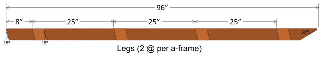
The A-frame assemblies are each made up of two angled legs and four horizontal shelf supports. The legs are milled from two 8-ft 2 x 4s. The 68 in. shelf support, and the 44 in. shelf support may be cut from one 10 ft. 2 x 4, and the remaining shelf supports (32 in. and 56 in.) may be cut from one 8 ft. 2 x 4. So the total requirement for one A-frame is 3 @ 8 ft. and 1 @ 10 ft. 2 x 4. The legs are milled in accordance with the diagram.
The A-frames are assembled by sandwiching the horizontal shelf supports between the legs. The legs are oriented so that the slots milled into them face inward. The legs are fastened together at the apex with three 3 in. deck screws. The shelf supports are secured into the milled slots in the legs with two 2 in. deck screws in each slot. The shelf supports are centered in the A-frame with a little over 1 ft extending on each side of the A-frame.

Milling the Legs
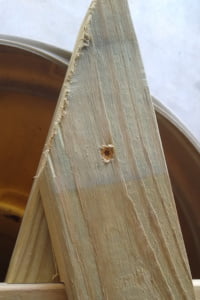
1 – Cut a 60° miter at the apex end of the leg.
2 – Cut about 1/2 inch off the apex end of the leg to minimize the chance of splintering, and to prevent the sharp point from piercing plastic covers placed over the plants in cold weather.
3 – Make a 15° miter cut at the base end of the leg.
WARNING – Make sure you cut the miter so that the short edge of the base is the same as the short edge of the apex. The two miters will form a trapezoid shape.
NOTE – The remainder of this section assumes the shelf support notches will be milled using a sliding compound miter saw. If using a radial arm saw or a router, adapt your own procedure for milling the slots accordingly.
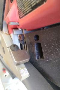
4 – Adjust the saw’s depth stop for a cutting depth of 3/4 inch.
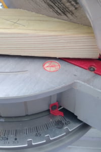
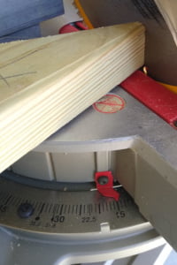
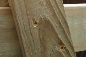
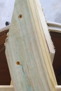
5 – Use the saw to mill out the four shelf support notches at the heights shown on the diagram. Set up the saw to make the cuts at an angle of 15°. You will need to place a 1 x 4 between the leg and the saw fence to hold the leg away from the fence so that the saw blade can cut to the 3/4 inch depth for the entire width of the notches. The notches are nominally 3-1/2 inches tall, but may need to be adjusted to ensure a snug fit for the shelf supports. For our project, the shelf supports were slightly wider than the nominal 2 x 4 3-1/2 inch width, so we had to mill the shelf support notches slightly wider to accommodate them. The shelf supports should fit snugly, but should not be difficult to push into the slots. Alternatively, the shelf supports could be ripped on the table saw to the same width as the leg notches.
WARNING – Make sure you cut the edges of the shelf support slots parallel to the 15° miter cut at the leg base.
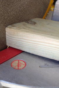
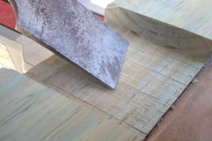
After milling out the shelf support slots use a wood chisel to clean out any thin slices of wood left over in the notches.
Assembling the A-Frames
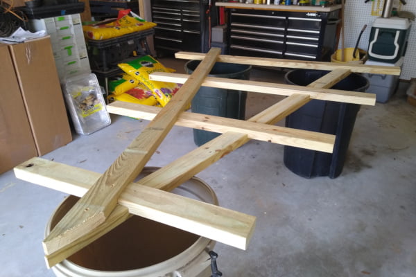
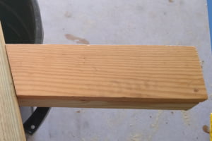
1 – Assemble the A-frames by sandwiching the shelf supports between the legs and pressing them into the leg notches. A simple alignment template cut from a short piece of 1 x 4 comes in handy to ensure the shelf supports are centered.
2 – Align the legs at the apex, and fasten together with a 3 inch deck screw.
3 – Starting with the bottom shelf support, fasten each shelf support into its two leg slots with two 2-inch deck screws per slot, driving into the shelf support through the leg. Ensure the shelf support remains centered in the A-frame with the centering template while the screws are being driven.
4 – Complete the assembly by driving two more 3-inch deck screws at the apex. These screws should be driven in the opposite direction from the one driven in step 2.
Building the Stand
If possible, the completed stand should be completely level, square, and plumb. This will make installation of the shelving much easier. However, some sites may not allow this. Even on an inclined site, it is absolutely essential that each A-frame is level and plumb. That is to say that the bases of the legs on each A-frame must be on the same level, and the apex of each frame must be directly above the midpoint of the line between the legs. Also, even if the A-frames “stairstep” up or down a slope, the distances between the legs of the A-frames must be uniform, and the A-frames must be squared to each other by making the diagonal measurements between each leg of each A-frame and the opposite leg on the next A-frame in line identical.
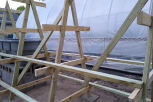
WARNING – As just stated, the A-frames must be plumb. Furthermore, some measure must be taken to ensure that they remain plumb. For our installation, we accomplished this by using 2 x 4 shelving to secure the distances between the adjacent A-frames, and diagonal 2 x 4 braces to prevent racking of the final assembly. Some other options might be cables, rods, and/or pipes.
Shelving
We used 8-foot 2 x 4s for the shelving on our plant stands – two boards were used for each shelf. The inner board was placed against the A-frame and the outer board was spaced 3-1/2 inches out from the inner board. The butt joints were staggered so that if the inner board of a shelf had a butt joint at one of the A-frames, the outer board did not, and vice versa. In lieu of 2 x 4s, pipes, 2 x 2s, exterior grade plywood, or cables could be used. Beware, however that the shelving on our project also provides rigidity to maintain the horizontal distances between the A-frames – an essential characteristic for the diagonal bracing to be able to maintain the A-frames in plumb. If cables are used for the shelving, some other means must be used to maintain the A-frames evenly spaced, and in plumb.